
Week 5 (3rd Period)
- António Morais
- Catarina Caramalho
- Tiago Teixeira
- 3rd Period - Weekly Progress
- March 17, 2024
3D Mapping
→ A-LOAM
This week, the team collected real data from the robot’s Ouster LiDAR to conduct testing with A-LOAM
. To achieve this, a launch file was created on a personal laptop to record data published on the rostopic /ouster/points, where the data from the Ouster LiDAR is published. After confirming its functionality with the simulation, the file was transferred to the real robot, and data collection commenced.

After assembling a dataset with real data, the team proceeded to test A-LOAM with it. Below is the map obtained from the testing:


Figure 2 - Map of the laboratory of systems and robotics (where the testbed is located), using A-LOAM with real data aquired from the robot's Ouster.
As one can observe, the result does not appear promising. However, this outcome was not attributed to the algorithm’s performance. Subsequently, we determined that the issue stemmed from teleoperating the robot at excessive speeds, resulting in nonsensical data acquisition.
To enhance the quality of the dataset, the team repeated the process several times. However, rather than attempting to capture a rosbag of the entire laboratory, the team initially focused on gathering data from the testbed.
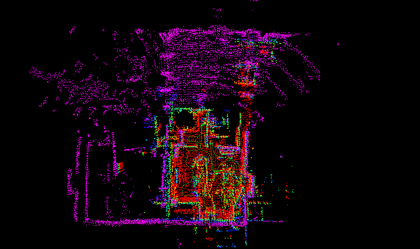
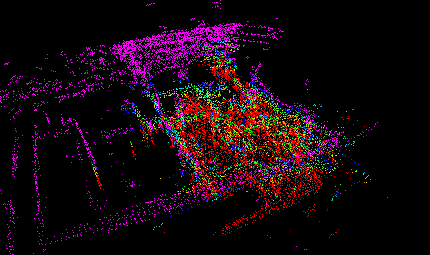
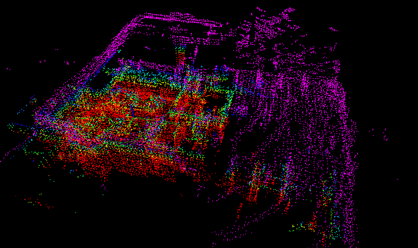
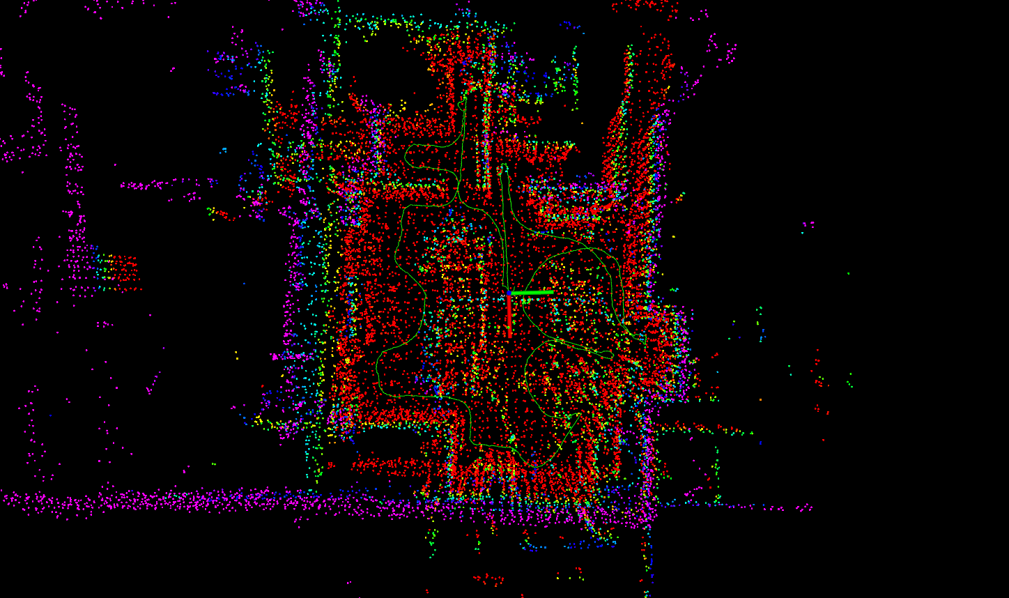
Figure 3 - Map of the testbed using A-LOAM with real data aquired from the robot's Ouster.
As evident, the result is considerably more conclusive as it now closely resembles the testbed itself. However, some non-desirable points are still detected, notably the reflection of the testbed caused by light reflecting off the windows — a common occurrence with LiDAR technology.
Subsequently, the team created a rosbag of the entire laboratory and achieved a satisfactory result, despite a disturbance caused by a dynamic obstacle (a person walking), as depicted in the forthcoming images:

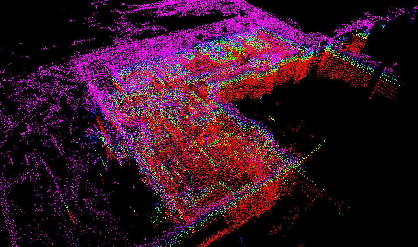


Figure 4 - Map of the laboratory of systems and robotics (where the testbed is located), using A-LOAM with real data aquired from the robot's Ouster.
Note that the red points, which appear to represent a lower floor, are also a result of light reflections on the varnished floor.
Additionally, the team utilized the pcl_ros
package to convert the simulation map obtained in Week 4 (3rd Period) into a .pcd file, which will be of use for the Localization team.
With this in mind, we can consider A-LOAM ready, and our primary focus moving forward will be on LIO-SAM . Eventually, it will be advantageous to create a rosbag without dynamic disturbances and noise caused by light reflections and use it with A-LOAM .
3D Localization
→ AMCL3D
During the first few weeks, the team concentrated on studying the AMCL3D algorithm, as mentioned in Week 2 (3rd Period). However, there were some setbacks when attempting to test the algorithm.
It was discovered that the algorithm was not compatible with ROS Noetic and Ubuntu 20.04 , as it was developed for ROS Kinetic and Ubuntu 16.04 . Furthermore, the GitHub repository lacked a Docker file to get around this issue. As a result, the team had to search for new alternative solutions.
Nevertheless, changing algorithms had its benefits since AMCL3D was designed for a drone and utilized input data from different technologies than what the team was using, making adaptation more challenging. The new alternatives have optional input data to facilitate the adaptation.
The mistake was starting to study the algorithm before testing it, as it is common to find numerous errors during the compilation of the algorithm, which can impede progress.
→ New Algorithm Alternatives
HDL Localization
The HDL Localization algorithm uses a 3D LiDAR (Velodyne HDL32). Utilizing Unscented Kalman Filter-based pose estimation, this package incorporates input data from an IMU (Inertial Measurement Unit) to estimate pose. However, the utilization of IMU data remains optional, and the team is currently evaluating whether to incorporate it or not. Despite its promising capabilities, this algorithm does not generate TFs (Transforms).

MCL3D
MCL3D is based on a fusion approach that combines Monte Carlo localitazion (MCL) and scan matching (SM) through importance sampling . This fusion method seamlessly integrates the strengths of MCL and SM while mitigating their limitations, offering a comprehensive solution for 3D localization tasks. Notably, this fusion method achieves accurate results with fewer particles, leading to computational efficiency without sacrificing accuracy.

2D Path Planning
This week, the team made significant progress in leveraging the point cloud generated by the Ouster for local and global path planning within the simulation environment.
To accomplish this, we made modifications to certain launch files, which were previously utilized to transmit the point cloud from the RGBD camera on the robot’s torso to the pointcloud_to_laserscan node. Given that we already had a ROS topic in the simulation where the Ouster points were being published, our task primarily involved developing the code necessary to relay these points to the node mentioned previously.
As shown in Figure 8, the robot is now capable of detecting the obstacles in its surroundings using the information provided by the Ouster.


However, the current configuration of the node assumes a fixed maximum height for obtaining points, which doesn’t account for potential changes in the robot’s height. To address this limitation, we need to modify the node’s code to enable dynamic adaptation to variations in the robot’s height. Consequently, we obtained the source code for the node from GitHub, and moving forward, we will need to manually compile it.
For the upcoming week, our objective is to successfully implement the necessary adjustment to the node.


