Progress Update (Circuit) - Week 6 to 12 of May
Our prototype must start with a circuit design. Neelam started with the research about what were the necessary connections to implement our prototype and designed the following circuit in “cirkit” with the help of Miguel Gonçalves. Let’s look into it in a more detailing way.
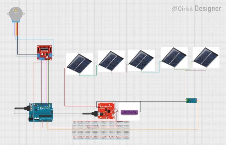
The stepper motor ordered is a 4 phase eight-stepping motor which means it is a bipolar motor. Firstly, the stepper motor was plugged into the Gear Stepper Motor Driver Board. OUT1, OUT2, OUT3, OUT4 (Output Pins are connected to the coils of the Stepper Motor). OUT1 and OUT2 are connected to the RED and ORANGE coils, while OUT3 and OUT4 are connected to the PINK and YELLOW coils, respectively. These outputs provide the necessary drive currents to the motor coils. This motor’s datasheet has explicit connections between the Gear Stepper Motor Driver Board to seeduino via jumpers. IN1, IN2, IN3, IN4 (Input Pins) are connected to the digital pins D8, D9, D10, and D11 of the Arduino UNO, respectively. They are used to control the direction and the stepping sequence for the stepper motor. 5V (Power Pin) is connected to the 5V pin of the Arduino UNO.
Other Arduino’s connections made are A0, which is connected to a voltage divider network formed by two resistors and A1 which is connected to the output of the Current Sensor. These pins are used to read analog voltages, which can be related to the voltage and current sensing, respectively. Additionally, there is a USB cable that directly connects to MPPT.
Solar cells are connected in series. Then, the current sensor in the circuit has the following pins: Pin 1: This pin is connected to a solar cell, where the current to be measured enters the sensor. Pin 2: This pin is connected to pin 2 of the MPPT, where the current exits the sensor after measurement. OUT: This pin is connected to the A1 analog input pin on the Arduino UNO. It outputs an analog voltage proportional to the measured current. Furthermore, the MPPT is connected to the 3.7 Volt lithium battery. Also, there is a connection to the Solar Cell and there is also a connected to the current sensor.
The ADC needs to compare the analog input with a known value which by default is the microcontroller supply. Otherwise, you won’t know what you are measuring. In this way the Arduino knows that maximum, so 1023 would be for 5V and minimum would be for 0V. There are a few things to consider: when there is a battery charged with 4V connected to the Arduino, if there is a ADC conversion, the chip will compare the measured 4V with the analog reference, and say its 4V and its 100% charged. Let’s say that after a while the battery voltage decreases to 3.8V, now the measure is the same as the VCC, therefore the analog read will give us the maximum once again, which is wrong. To avoid this problem, we fixed a value of voltage so that it won’t change with the battery voltage, ensured with the voltage divider. For this reason, we will use the INTERNAL reference which is equal to 1.1 volts.